LOGIC GATE | OR GATE | BUCKET OF PROJECTS
OR Gate
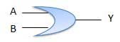
A circuit which performs an OR operation is shown in figure. It has n input (n >= 2) and one output.

www.tutorialspoint.com
Logic diagram
www.tutorialspoint.com
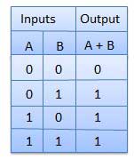
Truth Table
www.tutorialspoint.com
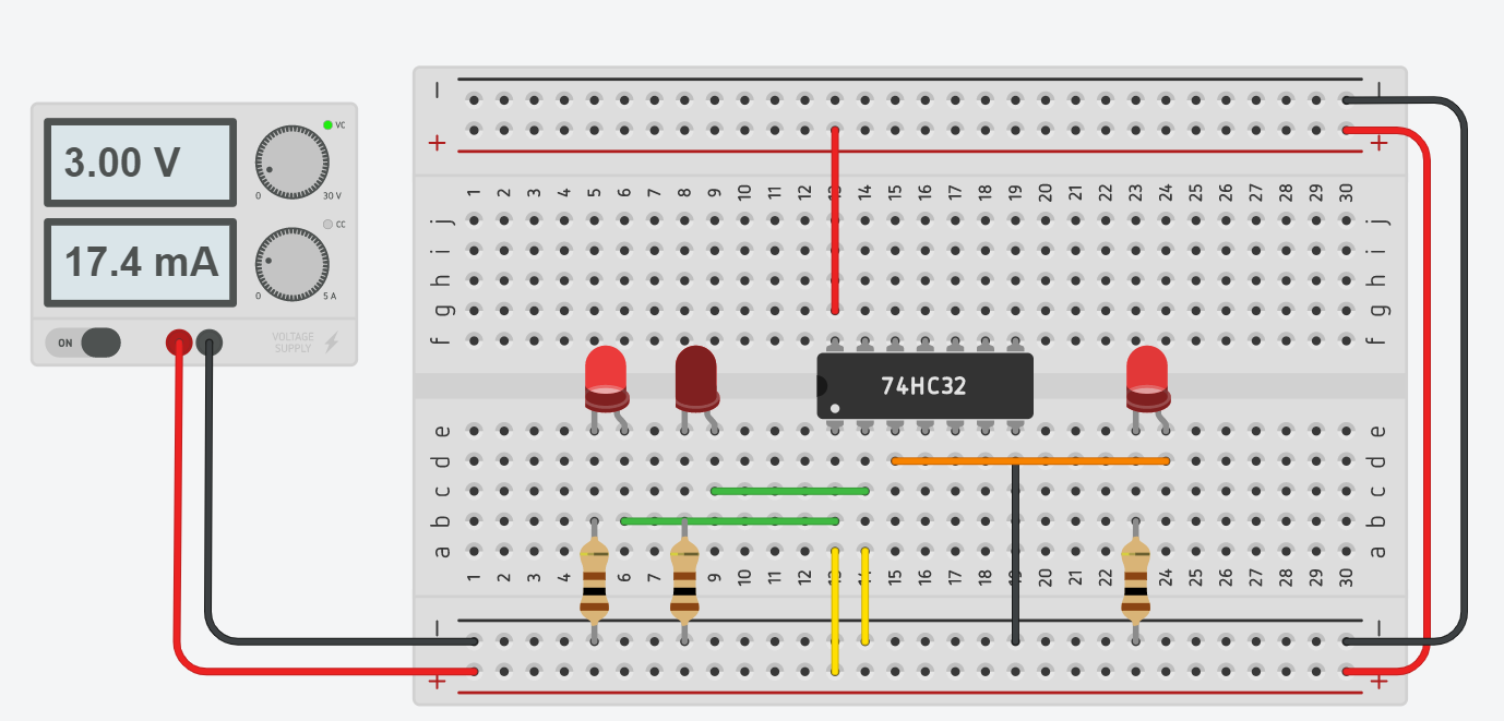
OR GATE IC
As we seen above, lets do using IC (7432)

components101.com
- Red wire is the Vcc / Power / + wire
- Black wire is the GND / Ground / - wire
- Green wire is the Red LED power wire
- Yellow wire is the input wire
- Orange wire is the Output wire


Very nice very useful
ReplyDelete