LOGIC GATE | NOT GATE | BUCKET OF PROJECTS

NOT Gate
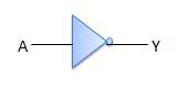
NOT gate is also known as Inverter. It has one input A and one output Y.

www.tutorialspoint.com
Logic diagram
 www.tutorialspoint.com
www.tutorialspoint.comTruth Table
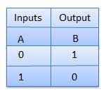
www.tutorialspoint.com
NOT GATE IC
As we seen above lets do using IC(7404)

electricaltechnology.org
- Red wire is the Vcc / Power / + wire
- Black wire is the GND / Ground / - wire
- Green wire is the Red LED power wire
- Yellow wire is the input wire
- Orange wire is the Output wire


Comments
Post a Comment