LOGIC GATE | NAND GATE | BUCKET OF PROJECTS

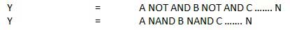
NAND Gate
A NOT-AND operation is known as NAND operation. It has n input (n >= 2) and one output.
www.tutorialspoint.com
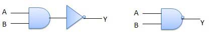
Logic diagram
www.tutorialspoint.com
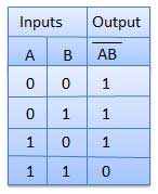
Truth Table
www.tutorialspoint.com
NAND Gate IC
As we seen above lets do in IC

nutsvolts.com
- Red wire is the Vcc / Power / + wire
- Black wire is the GND / Ground / - wire
- Green wire is the Red LED power wire
- Yellow wire is the input wire
- Orange wire is the Output wire
1) When the input both are 0 output will 1

2) When the inputs are 0 and 1 output will 1

3) When the inputs are 1 and 0 output will 1

4) When the input both are 1 output will 0


Comments
Post a Comment