LOGIC GATE | AND GATE | BUCKET OF PROJECTS

AND Gate

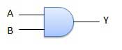
A circuit which performs an AND operation is shown in figure. It has n input (n >= 2) and one output.

www.tutorialspoint.com
Logic diagram
 |
www.tutorialspoint.com
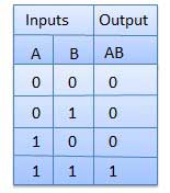
Truth Table
www.tutorialspoint.com
AND Gate IC
As we seen above lets do in IC (7408)

https://en.wikipedia.org/wiki/AND_gate
- Red wire is the Vcc / Power / + wire
- Black wire is the GND / Ground / - wire
- Green wire is the Red LED power wire
- Yellow wire is the input wire
- Orange wire is the Output wire
1) When the inputs are both are 0 output will 0

2) When the inputs are 0 and 1 output will 0

3) When the inputs are 1 and 0 output will 0


Comments
Post a Comment